Overview
Real G-code from geometry parameters — with instant 3D toolpath visualization
A web-based CNC G-code generator that converts user-defined geometry into
machine-ready G-code programs. Users configure tool settings, choose an
operation type, define dimensions — and instantly see the generated toolpath
in 3D, a 2D top-view projection, and the complete G-code output ready for
download as a .nc file.
The Problem & Why It Matters
CNC programming is a core mechatronics skill that bridges digital design and
physical manufacturing. In practice, engineers use CAM software to generate
toolpaths — but understanding what happens underneath (coordinate systems,
G-code commands, toolpath strategies) is essential.
This project builds a G-code generator from scratch — no CAM software, no
black boxes. Every G0 rapid move, every G1 cutting move, every M3 spindle
command is generated programmatically from geometry parameters. The result
is real, machine-executable code that any CNC controller can read.
Live Dashboard
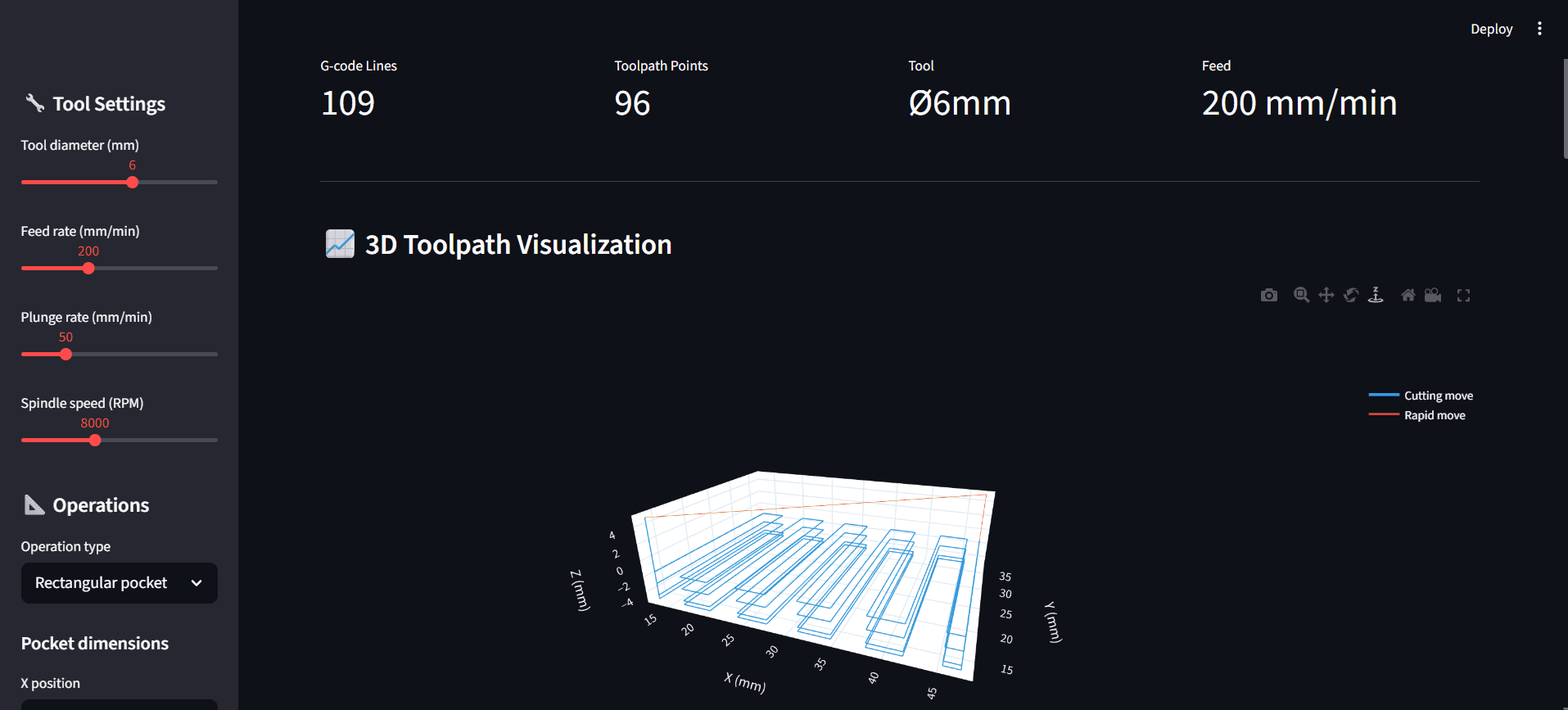
Dashboard overview — KPI metrics update in real-time as parameters change.
3D toolpath visualization shows the rectangular pocket zigzag milling
pattern with multi-pass depth layers. Sidebar controls for tool diameter,
feed rate, plunge rate, spindle speed, and geometry dimensions.
What It Does
🔧 4 Operation Types | Rectangular pocket (zigzag), circular pocket (spiral), bolt circle with peck drilling, and combined multi-operation parts. |
📊 3D Toolpath Visualization | Interactive Plotly 3D view — blue lines for cutting moves, red lines for rapid traverses. Rotate, zoom, pan. |
🗺️ 2D Top View | Bird's-eye XY projection shows the cutting pattern with tool-radius-compensated boundaries. |
📄 Real G-Code Output | G0, G1, G90, G21, M3, M5, M30 — proper program structure with header, operations, and footer. Copy or download. |
⬇️ Download .nc File | One-click export of the complete G-code program as a .nc file — ready for any CNC controller. |
⚙️ Full Parameter Control | Tool diameter (2–12mm), feed rate, plunge rate, spindle speed, depth, step-down — all adjustable live. |
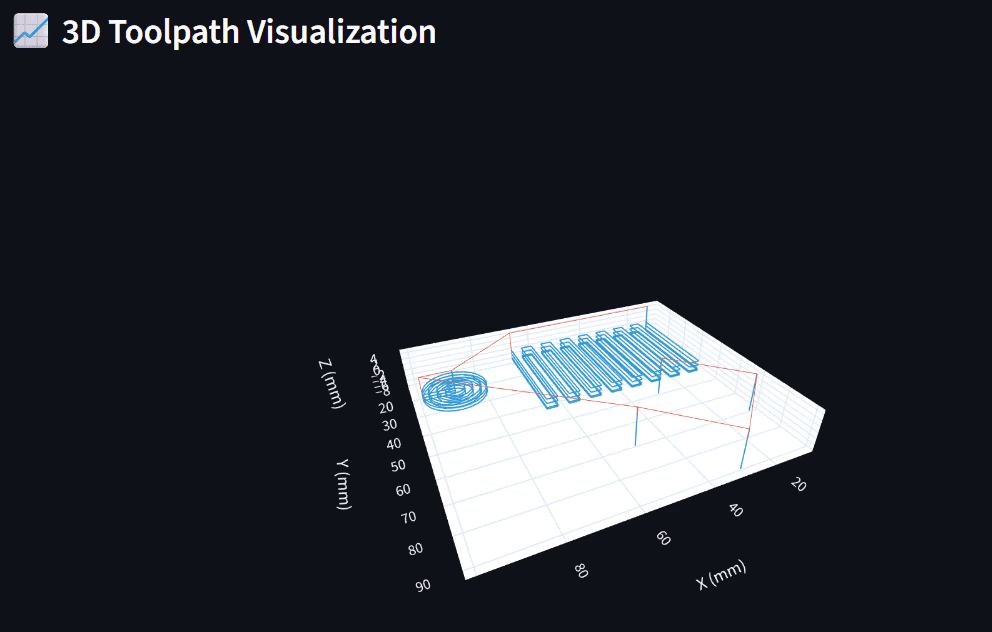
3D Toolpath — Combined Part View
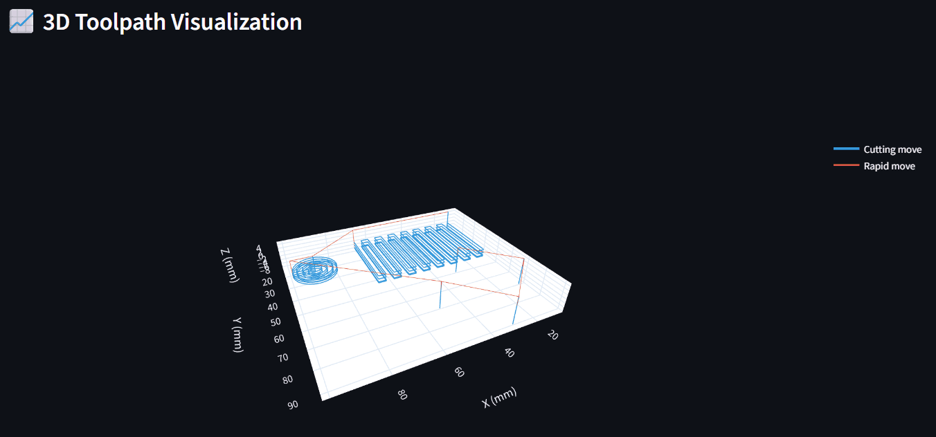
The screenshot showing the full 3D visualization with all three operation types visible — spiral (left), zigzag (center), and bolt circle drill holes — with blue cutting and red rapid move lines and the legend
The combined part view shows all three toolpath strategies in a single
program:
Rectangular pocket — zigzag milling pattern with 60% step-over,
multi-pass depth layers clearly visible as stacked blue pathsCircular pocket — spiral-out strategy starting from center,
expanding outward with adaptive point densityBolt circle — four peck-drilled holes evenly spaced on a circle,
with chip-clearing retracts (vertical blue lines)
Red lines show rapid traverses (G0) between operations — the tool
lifts to safe height, repositions, then plunges to the next cut.
🔵 Blue = Cutting moves (G1) — tool is in the material
🔴 Red = Rapid moves (G0) — tool repositioning above workpiece
2D Top View (XY Plane)
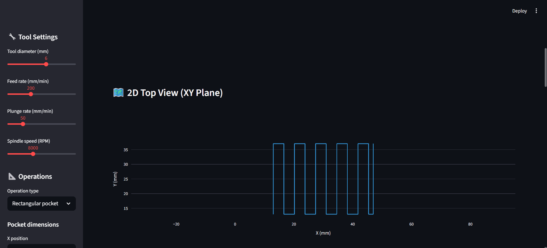
The screenshot showing the 2D bird's-eye view of the zigzag toolpath pattern with the sidebar visible on the left.
The 2D top view projects only the cutting moves onto the XY plane —
rapid moves are filtered out. This gives a clean bird's-eye view of
the actual material removal pattern.
For the rectangular pocket, you can see the zigzag strategy clearly:
the tool starts at the bottom-left corner (offset by tool radius),
sweeps vertically, steps over by 60% of the tool diameter, and
reverses direction. This continues until the full pocket width is
covered.
The 3.6mm step-over (60% of the 6mm tool) ensures adequate overlap
between passes for a clean surface finish — matching real-world
CNC best practices.
Generated G-Code
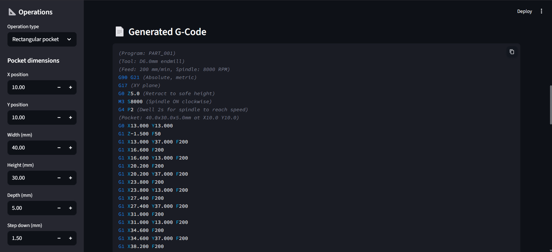
The generator produces real, industry-standard G-code with proper
program structure:
Header:
G90 G21— Absolute positioning, metric unitsG17— XY plane selectionG0 Z5.0— Retract to safe heightM3 S8000— Spindle ON clockwise at 8000 RPMG4 P2— 2-second dwell for spindle spin-up
Operations:
G0 X__ Y__— Rapid positioning to start pointG1 Z-1.500 F50— Controlled plunge into materialG1 X__ Y__ F200— Linear cutting moves at feed rate
Footer:
M5— Spindle OFFG0 X0 Y0— Return to home positionM30— Program end
Every command follows standard RS-274 G-code syntax — the output
file is directly executable on any GRBL, Fanuc, or LinuxCNC controller.
Live Demo
Note: If the screen says "This app has gone to sleep due to inactivity." please click on restart app.