
Overview
A PLC program controlling an automated 6-hole drilling station — built in
CODESYS using IEC 61131-3 Structured Text. A 9-state machine sequences
clamping, spindle start, coolant, drill feed, dwell, and retract with
safety interlocks for emergency stop and tool breakage. Operator HMI
with status lights, controls, and live data. Concept for Airbus automated
drilling lines.
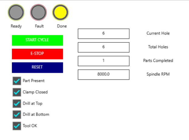
Cycle complete — all 6 holes drilled successfully. Yellow "Done" lamp
lit, part counter incremented to 1. All sensor interlocks confirmed
(part present, clamp closed, drill at top, tool OK). Operator presses
RESET to return to idle for the next part.
What It Does
Feature | Detail |
|---|---|
🔄 9-State Machine | IDLE → CLAMP → SPINDLE → COOLANT → FEED → DWELL → RETRACT → CHECK → COMPLETE. State 99: FAULT handler. |
🛡️ Safety Interlocks | E-Stop: immediate all-stop. Tool breakage: mid-cycle fault detection. Clamp interlock: drill cannot start until clamp confirmed. All checked every PLC scan cycle. |
🖥️ Operator HMI | 3 status lamps (ready/fault/done), 3 control buttons (start/e-stop/reset), 4 live data displays, 5 sensor toggle switches. |
⚡ Multi-Hole Sequencing | Automatic loop through 6 holes. Counter tracks current hole and parts completed. Returns to FEED DOWN after each retract until all holes done. |
📐 I/O Circuit Design | Tinkercad wiring diagram: Arduino Uno + 3 pushbuttons with 10kΩ pull-downs + 3 LEDs with 220Ω current limiters. |
🏭 Airbus Concept | Matches A321 automated drilling lines (Toulouse) and Hamburg riveting systems producing 5,000 fuselage shells/year. PLC programming is the #1 skill for manufacturing automation roles. |
State Machine in Action
State 0: IDLE
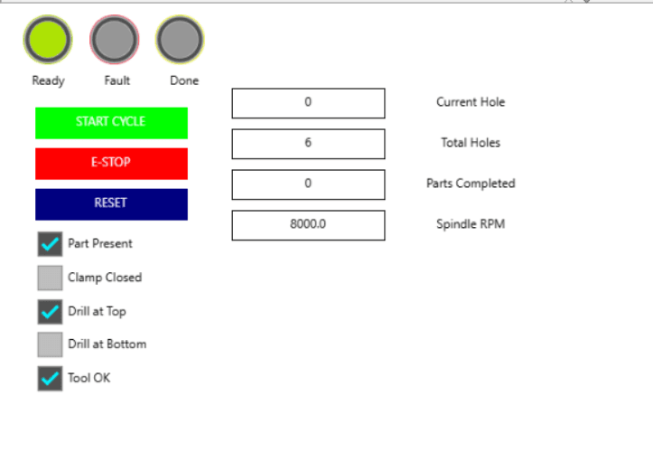
Green "Ready" lamp lit. System waiting for start conditions: part
present, drill at top, tool OK, no emergency stop. Current Hole: 0,
Parts Completed: 0. Note: Clamp Closed is unchecked — clamp only
activates after START CYCLE is pressed.
State 4: FEED DOWN
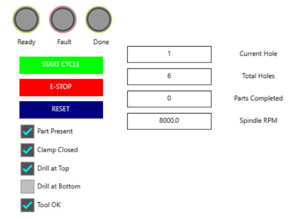
Drill is feeding down into the workpiece on hole 1 of 6. All sensor
interlocks confirmed except "Drill at Bottom" — the drill hasn't reached
full depth yet. Once the bottom sensor triggers, the state machine
advances to DWELL (500ms hold at depth) then RETRACT.
State 99: FAULT
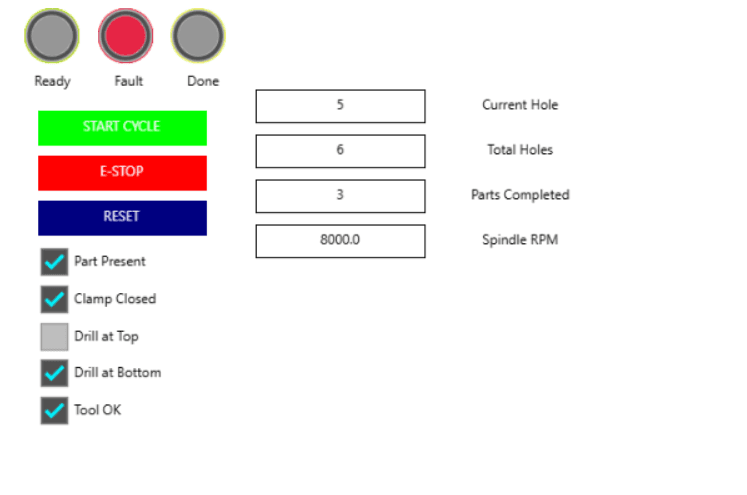
Fault triggered mid-cycle at hole 5 of 6 (3 parts already completed).
Red "Fault" lamp lit. "Drill at Top" unchecked — drill was mid-stroke
when the fault occurred. All outputs immediately killed: spindle OFF,
feed OFF, coolant OFF. Recovery requires clearing the fault condition
then pressing RESET.
Structured Text (IEC 61131-3)

Live simulation in CODESYS — variable pane shows eState = 5 (DWELL),bCycleRunning = TRUE, bFault = FALSE. Implementation pane shows
the emergency stop check (runs every scan), tool breakage detection,
and the CASE state machine. TON timers handle clamp delay (800ms),
spindle spin-up (1s), and dwell (500ms).
I/O Wiring Diagram
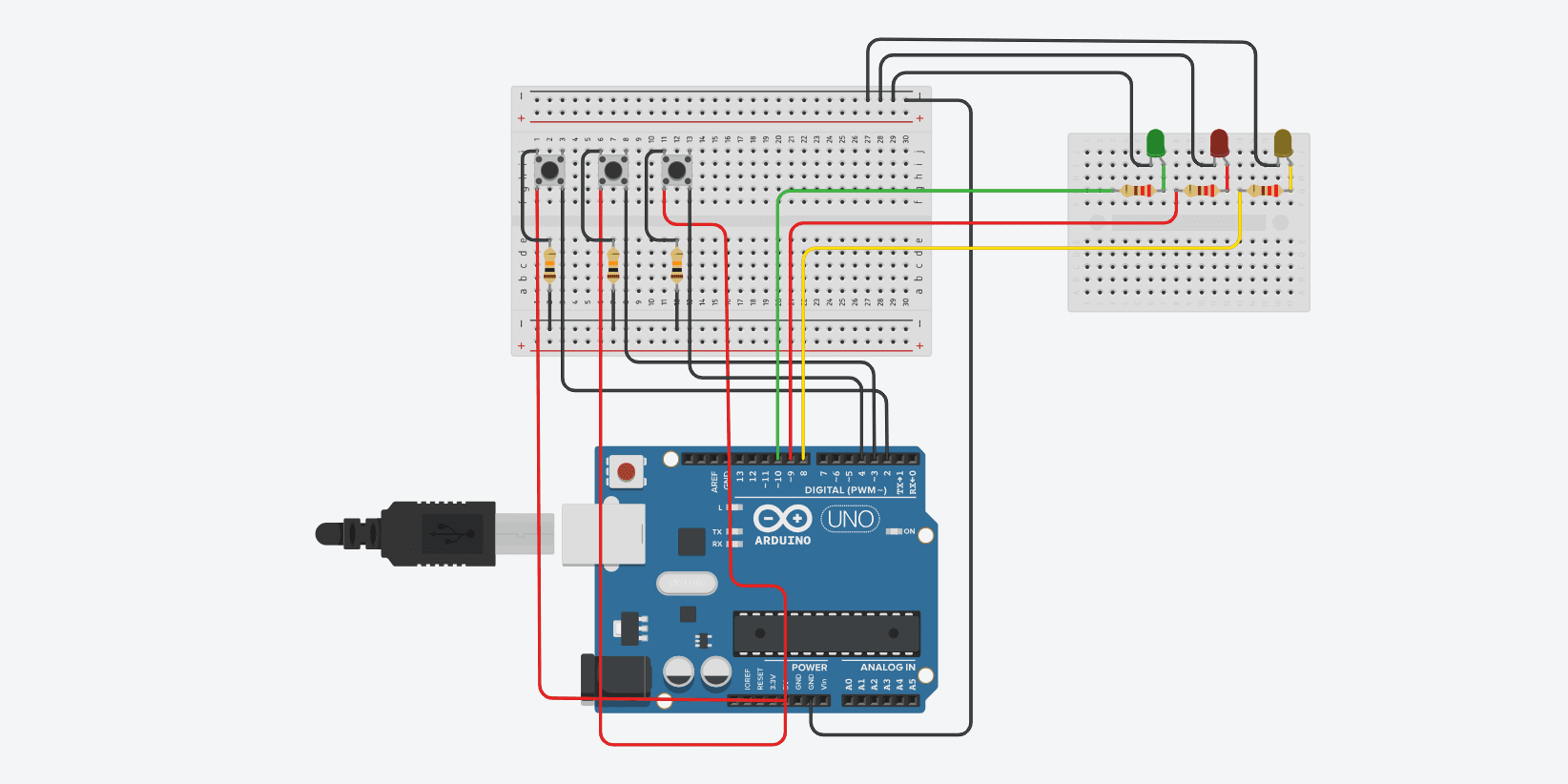
Arduino Uno representing the PLC controller. 3 pushbuttons (Start,
E-Stop, Reset) with 10kΩ pull-down resistors. 3 LEDs (green/red/yellow)
with 220Ω current limiters. Inputs left, controller center, outputs right
— standard PLC I/O layout.